RC2014 Troubleshooting Log
I assembled my RC2014 Plus in early 2018 and never got it to boot. Starting in October 2020, I’ll try to get it working again.
For the uninitiated, the RC2014 is a hobbyist computer you put together from a kit. While I had my frustrations getting it running, I highly recommend it to anyone interested in vintage computing, anyone learning to solder, or tinkerers in general.
While discussing my efforts to get the board to boot with a few online friends, I was asked to keep a log of my progress, so I did. As a fan of Clifford Stoll’s The Cuckoo’s Egg, I know the importance of keeping good notes and I’m happy to share my findings. Be warned there may be asides and ramblings ahead. I suppose that sometimes it is also good to record what you’re thinking about even if it doesn’t directly relate to the problem at hand. In any case, this is a bit unpolished and not edited with as much care as I normally take, but hopefully it is informative.
Without further delay, here is the log!
2020-10-17
When I couldn’t get my RC2014 to boot years back, I put it in a box to play with “later” and then forgot where I put the box. I discovered the box again a few months ago and think now is the time to work on it again until I can finally get it booting. So, let’s open the box and see what we are working with.
First thing I noticed is that the header was soldered onto the wrong side of the ROM module. This was daunting for me to fix in 2018, and unless I put that board in a particular slot, I couldn’t seat things properly. Mind you, this board is still functional (as far as I know), but I viewed this backwards header as a defect and I wanted to fix it. It was easy to desolder with a Hakko FR-301. This was maybe my second time using it, but I picked up the general idea of it quickly: place the nozzle over the pad until it heats up, maybe give it a little swirl, and press the button to vacuum while lifting away from the board. From what I understand it is important to run the vacuum for a few seconds after the solder is removed (I don’t remember where I heard this) and from trial/error I found that it was pretty vital to hold the gun at a 90 degree angle (over the pin) so that the nozzle was fairly flush with the board. I did mar the solder mask a bit, but it doesn’t seem like I did any major damage or burn the board. I also found that sometimes there were trace amounts of solder left holding the header to the board, so I had to add some fresh solder and try again. In total it took maybe 5-10 minutes to remove the 39 pins. I did end up destroying the header while removing it in favor of soldering on a new one, which may have made the process a bit faster. I’ll solder the new one on at a later date, no time right now.
After reviewing the RC2014 website, I could not find good assembly instructions for the Plus, which is likely why I’ve associated assembly with frustration for a bit. If you have a standard RC2014, there are tons of well done instructions, though. Most modules have their own page on the site with a schematic, however, which is good. When I inquired previously about assembly instructions, I was told to consult the images on the Tindie storefront, which works in the absence of formal instructions.
Reviewing the images, I noticed that I was missing a few resistors on the serial board, and I’m not quite sure why I didn’t put them there. Maybe it was possible that I didn’t get them in the kit for some reason, but I’ll add them later to match the pictures. I also only ever tested the serial with a cheap MAX232 based serial board, so let me get a proper FTDI cable as well. I ordered an Adafruit-branded one. [tj] taught me to not skimp out on stuff like these after I had similar issues with TTL comms in the past.
It is very possible I never got a proper serial session set up and things will work perfectly, but I’ll wait for the FTDI cable and try it out with that. If it doesn’t work, I’ll add the resistors and try again.
2020-10-20
Soldering the new header on the proper side progressed fairly quickly. Having some no-clean flux definitely helped, I didn’t have this when initially putting the board together and I wish I did. I did notice that one of the pins I was soldering did not seem to want to adhere to the pad. The only explanation I have is that I somehow broke the pad when removing the header, so maybe don’t be as hasty as I was. I did notice that there appears to be some solder that traveled through the hole to the pad on the other side of the board, and there is continuity between this pin and a leg on the rom socket, so I imagine everything is fine. Had I completely butchered this, I would likely have taken some wire-wrap wire to bodge the pin on the header directly with the proper leg on the ROM socket.
At this point I have my FTDI cable and want to get a session. The computer on my workbench runs MacOS for some reason, so we will use that. Plugging the cable into the Mac seems to make it show up when running ls /dev/cu.* so good signs so far. I connected the cable to the serial module aligning the black wire with the ground pin. It is important to note that I do not have the jumper to power the RC2014 via FTDI, so I am using the barrel jack with a supplied cable that hooks up with a USB/wall adapter. Starting the screen session on the Mac with something like screen /dev/cu.usbserial 115200 (the bitrate is specified by the RC2014 site). and then powering on the RC2014 yields nothing on the console. I believe that this is normal and you need to hit the reset button on the RC2014 to kick things off, so I did that and again, nothing on the console.
Now it is time to solder the three resistors on the board that I hinted to the other day. Luckily I have these in my parts stash, so no order or waiting necessary. After soldering these in, I attempted the power-up-and-console-testing process again and no luck. To try ruling out something like inadequate power (Maybe that barrel-to-usb cable is bad?) I connected the jumper to power the RC2014 via FTDI. Plugging the FTDI cable into the Mac after this seems to power the board, so that’s something cool. However, still nothing on the screen after hitting the reset button.
As a last ditch effort to rule out the Mac, I connected the board and FTDI cable to a Raspberry Pi to test the console from there. Again, running screen /dev/ttyUSB0 115200 gave me nothing on the screen after a reset button push.
Next steps will be to recheck the boards against the Tindie images to make sure they are correct and then follow the steps on the RC2014 site for multimeter testing.
2020-10-21
So it looks like there were two cases of pads that needed to be jumpered together that I did not jumper. One was missing on the clock module near the top left and the other was near the middle of the serial module.
Soldering the headers onto these locations and jumpering them just took a minute or two. Testing again for serial console again yielded nothing.
Now it was time to do continuity tests. I flipped the backplane over and made sure that there was continuity between like-pins by using a multimeter and probing them horizontally. The way the 8-slot backplane is set up, slots 3-6 are all completely linked horizontally while slots 1, 2, 7, and 8 are partially linked. You can fully link these slots by jumping more pins, but with my module configuration this doesn’t seem necessary as long as I keep the clock module in slot 2. I suppose the clock only needs that subset of pins that are linked.
This continuity test was successful so I then went across each pin on the modules to make sure that no two pins are bridged here. Everything seemed okay, though the RAM module would appear to have some bridging. I believe this is from capacitors charging up and discharging, but this could be a potential issue.
I then checked to make sure each board was getting power properly. I set my multimeter to DC voltage and probed the power and ground pins of each module while the board was powered on. I got voltages of around 4.1-4.2. The RC2014 site says that you should see power between 4.8 and 5.1 volts, but I don’t know if there is a different spot I should be probing for this, or if this is what the boards should be reporting. This could also be an issue. I also tried using a different wall adapter for power and got similar voltages. I still need to check voltages when powering via FTDI to see if anything is different there.
At this point I also tried out some oscilloscope testing. I have an old 10MHz, 1-channel CIE scope that is much older than me and I have never really used it. Based on the RC2014 site, probing the clock lead on the clock module should provide a sort of squarish wave that can be viewed. I’m not too experienced with my scope, but I tried to see if I could get this wave to show and I did not. I did get a sine wave when looking at millivolts, but the same wave appears when I probe the power lead on the module, so this is likely just small fluctuations in the voltage. I did notice that monitoring these leads and then holding the reset button on the backplane yielded a flat line on the scope, so the scope does appear to be working somewhat.
At this point it seems like I don’t have clock signal. Again, this may be power related, but first I once again want to double-check my modules against the Tindie images before posting to the RC2014 Google group with questions.
I saw on the RC2014 site that there is a basic test circuit that could be built in lieu of an oscilloscope, so I ordered the $1 worth of components from Digi-Key to build it as well since why not. In the spirit of overkill, I also ordered a vintage function generator that I can hook up to my scope to see if it can display different waveforms. Of course if I don’t see anything on the scope I have no idea if the scope or generator is at fault, but both of these components were inexpensive enough that it isn’t much of a loss either way.
2020-10-22
Just for a sanity check, I did a continuity check on the reset button and this seems to be wired properly.
I decided to try calibrating my oscilloscope after tracking down a digital copy of the manual. Calibrating seemed to be working well, and it looked like there might have been some adjustment I needed to do for the amplitude of the sinusoidal wave, but after getting this far I ended up hearing a loud pop and smoke started coming out of the oscilloscope. I’m guessing a capacitor blew up. The unit still seemed somewhat functional but I immediately unplugged it. I don’t think there is a service manual available to see what components go where, so hopefully whatever blew up has some legible markings and didn’t disintegrate. Ultimately it may not be worth repairing.
2020-10-27
I got a new oscilloscope locally, just something cheap nearby. It works, but it seems like it might be too basic for my needs as it turns out to be a 5MHz scope and the clock module operates over that. The oscilloscope itself is very interesting, though. It is a Bell-Howell model that was used by DeVry students back in the ’70s. I’m not sure if students assembled it themselves or bought it for classes, but it seems to work fairly well and I fed it some basic stuff from my function generator that gave me nice visuals. I think I should just bite the bullet and get a nicer scope
2020-11-08
I decided to spend a bit more money and be a bit more selective about which scope I wanted and settled on a Tektronix 2246 that has everything I’ll need and a bunch I won’t. I ordered it from eBay a few days ago and it arrived today. I didn’t do much more than power-test it and hook a probe to the calibration point to make sure I see some sort of wave on the screen (which I did, hooray!). It’ll likely be a bit before I get to probe the RC2014 with it but at least I have it now.
Work has been crazy, so I’m not sure when I’ll get to test things further.
2020-12-15
After a long time (and the start of my winter break), I decided to hook my oscilloscope up to the clock pin and see what was going on. Setting the oscilloscope to 2v/50ns as the troubleshooting steps suggest yielded nothing but a flat line on my scope. I tried the reset button on the RC2014 a few times, which would make the line wobble a bit, but no clock was to be found. Tomorrow, I want to check it again and maybe take some pictures of the board to accompany a help email to the Google group.
2020-12-16
Today I repeated the same steps from yesterday, finding no change. I removed the clock module from the backplane and upon flipping it over I found that I only soldered half the header pins. I don’t know how I never noticed this before, and I have no idea why I didn’t solder all the pins. Maybe I got halfway through and was going to come back to it but never did? Anyway, I fired up the soldering iron and got to soldering all the pins. I recently installed a new blade tip on my Hakko iron and I’ve been wanting to try out drag-soldering which I learned from watching wonderful videos by Voultar. After a few seconds I had all the pins soldered in and decided to rework some older ones on the board that didn’t look bad but were a bit blobby. This felt like the fix I needed, but would it work?
I put the clock module back in the backplane, placed the scope probe on the clock pin of the clock module and the ground clip to ground. Upon powering the RC22014 via barrel plug, I noticed that my oscilloscope now displayed a thick bar across the screen. This is different, so I adjusted the time division lower and saw a wave. Success! It wasn’t super squarish, but I had something. After reviewing the manual for my scope I’m still not entirely sure how to properly calibrate it, but at least I now had something oscillating on the screen. Powering off, connecting the FTDI cable and then powering on still yielded nothing in a console session. I unplugged everything and then set the jumper on the serial module to power the RC2014 via the FTDI cable. Plugging the FTDI cable back into my computer and starting a session again also yielded nothing.
At this point I remembered that I had previously seen low voltage with a multimeter when probing 5V and GND. Now that the clock was sort of working, I thought I would give it a try. Using a series of clip-on probes, alligator leads, and my multimeter probes I was able to connect to the proper pins on the clock module to take my reading. After removing the serial module power jumper and applying power to the RC2014 board via barrel jack I observed a reading of 3.9V which is far lower than the expected 4.8V-5V. I thought it may have something to do with the components soldered onto the backplane, maybe a wrong resistor or something, but I feel like that was unlikely as I matched the Tindie pictures.
At this point, I thought it was time to go to the RC2014 Google group to ask about this weird power reading I was getting. I noticed you had to request membership to the group to be able to post, so after submitting my request I browsed through some of the current messages. I did a search on a whim for “voltage” to see if anyone had the issue that I was seeing and there was one message from someone seeing a low voltage on a single module when it was the only one inserted into the backplane and all the other modules show proper voltage when they are the only ones inserted. Comments asked for picture of the module to diagnose it, and I figured this might be the next steps for my issue so I might as well do the troubleshooting now. I removed all the modules from my backplane except the clock module and powered the RC2014 again. This time I got about 4.9V on the multimeter, so the clock module looks good! I then tried again with the clock module in slot 3 on the backplane instead of slot 2 to see if that slot was working okay and supplying the same voltage. After powering off, moving slots, and powering on I was getting the same voltage so slot 3 was good as well. I moved the clock module back to slot 2 so I wouldn’t have to keep reattaching probes and put the RAM module in slot 3. After powering up, I was getting around 4.8V, a good sign for the RAM module. I swapped the RAM module with the CPU module and powered on to a low 4.3V. Okay, something is wrong with that, but let’s see if anything else is low. Swapping CPU for the ROM module produced proper voltages, but then swapping for the serial module gave another low reading.
Okay, so what was wrong with the CPU and serial modules. I decided to start with the CPU module since this was perhaps the most basic module in the whole machine; there isn’t much that can go wrong. Upon inspection, the solder traces looked good, so I pulled up the assembly pictures from Tindie once more to compare. It was at this point I noticed that the wrong chip seemed to be in the CPU socket! The CPU module and the serial module both use Zilog-branded 40-pin chips and I had swapped them this whole time. Surely I should have recognized that one read “CPU” and the other read “SIO” but I suppose I never looked that closely.
Something that you might not know about me is that I am terrified of pulling chips out of sockets because of one bad experience years back where I managed to completely snap a leg off of a Z80. I armed myself with a a small flat-head screwdriver and this nice little Japanese chip puller I bought specifically for the RC2014 years back made by Engineer. I cannot recommend it enough over the cheap pullers on eBay. Anyway, I used the screwdriver to work up the edges on each chip just enough to slide the tongs on the puller underneath on both sides and then locked the puller in position. If you rest the module flat on a table and pull the chip puller straight up, the chips come out quite easily. After getting both chips out, I inspected the pins to make sure they were straight (if they bow outwards a little you can “roll” them a bit on the table to get them all properly aligned) and put the proper chip in the proper socket.
I then tested the CPU and serial modules in slot 3 and got proper voltages each time. Now it was time to get everything back in the backplane, so I inserted the cards, connected the FTDI cable, and made sure my multimeter was ready to go. Upon power up, I saw 4.8V on the multimeter. Good sign so far. With my console session on my PC ready, I tapped the reset button on the backplane and the console sprung to life!
Finally I had the RC2014 booting. I tapped the return key on my keyboard to initialize the memory settings and was greeted by Microsoft Basic, where I wrote and executed a little “Hello World” one-liner.
That’s the end, everything works well now and I can finally play with the system.
Conclusion
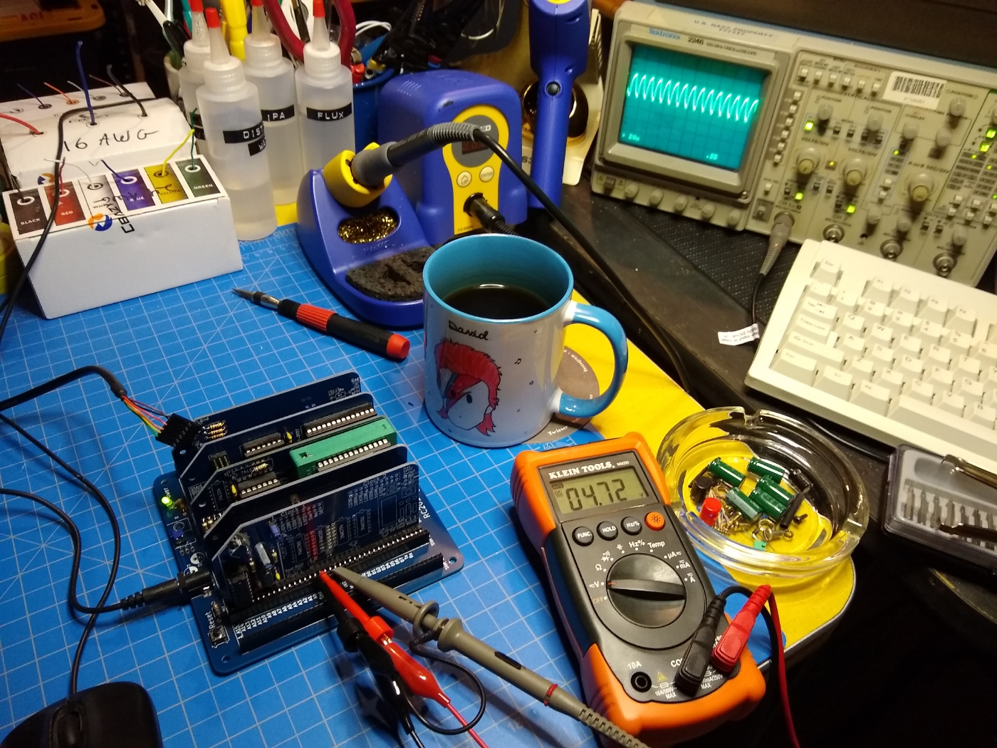
The RC2014 running and working.
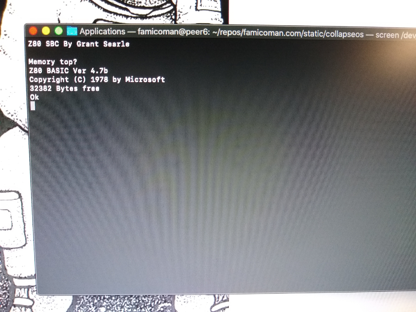
Checking the RC2014 console.
After around 3 years of work, I finally have a working RC2014 system. Aside from just playing with it some more, I have plans to swap out the 40-pin CPU socket for a low-profile ZIF socket so I can easily swap in different CPUs as I have an old Soviet-made Z80 clone I’d like to try out and it might be cool to get other clones or vintage Z80 chips.
At some point in the future I would like to play with CP/M since I never have before, so I will do some hardware upgrades to accommodate that.
If you have any suggestions for cool projects to do with the RC2014 (I’m already aware of running CollapseOS and creating a super-slow web-server) feel free to reach out to me!