Connect a Wyse Terminal to a Raspberry Pi
I love old terminals. I love amber and green phosphors. It just sort of feels like doing real computing. Unfortunately these days, you don’t see a lot of terminals in day-to-day life, but they are available for sale on the second-hand market.
If you’re lucky to snag an old Wyse terminal, don’t get intimidated! They are fairly easy to connect to modern computers, even Raspberry Pis.
Below I will show two ways to connect a terminal to a Raspberry Pi 3: through the UART or via USB adapter.
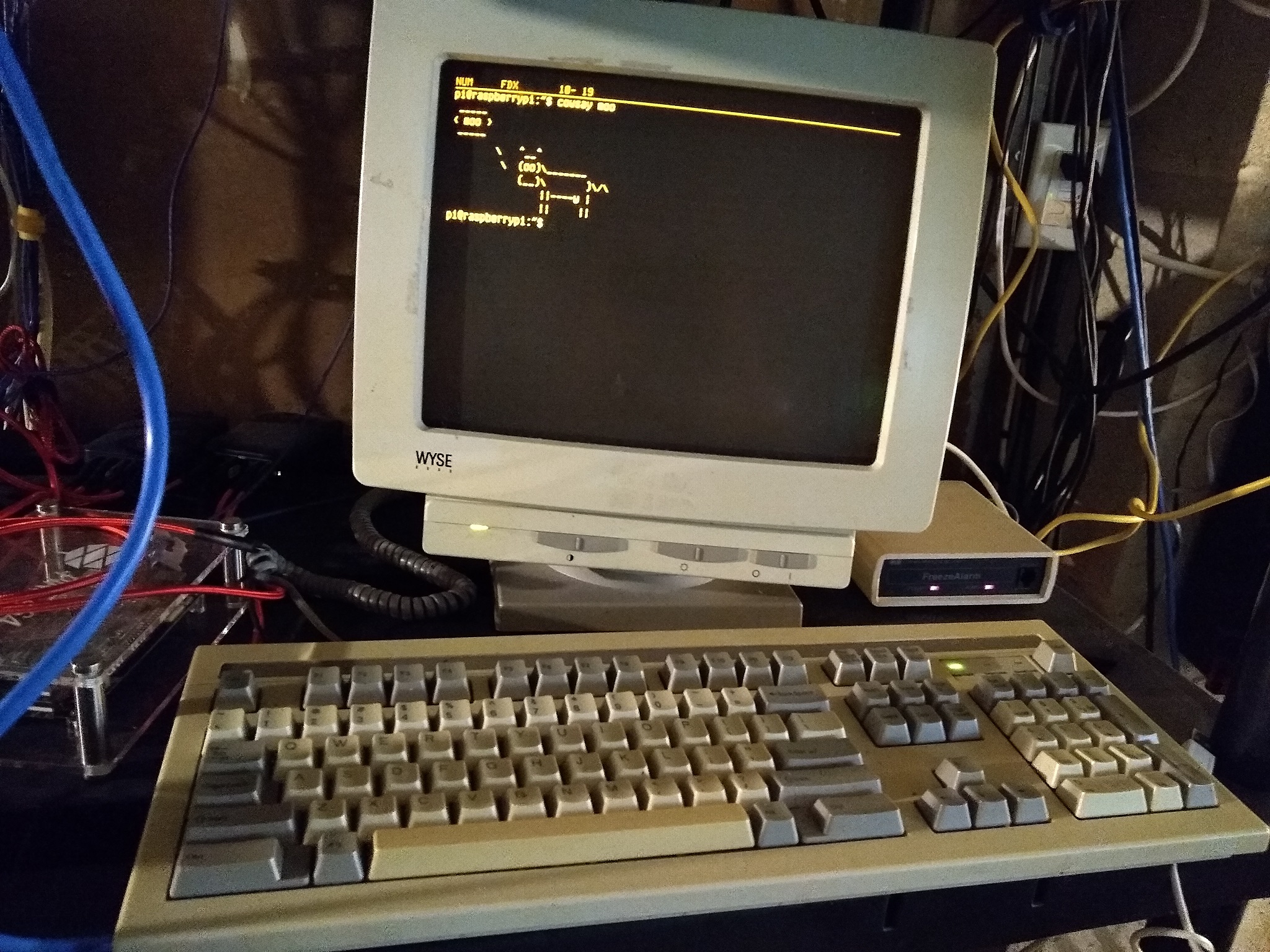
A Wyse terminal displaying cowsay.
Before You Begin
So you have a terminal and a Raspberry Pi, what next? I’ll first assume that you have a power cord for the terminal and all the standard supplies for the Raspberry Pi (power cord, microSD card, etc.) and otherwise have the Raspberry Pi booting an operating system like Raspbian. I’ll also assume that you have a keyboard for the terminal so you can use it… as a terminal. Note that most (if not all) Wyse terminals appear to use RJ-9 connectors for their keyboards, and you likely cannot adapt another keyboard connector to use on the terminal. Even if you are somehow able to “hijack” the session between your Raspberry Pi and terminal to get something on the screen without having to input from the terminal itself, you will probably have to go through some configuration on the terminal itself (and that requires the keyboard).
Configuring the Terminal
Before we hook the terminal up to a Raspberry Pi, we need to check the terminal’s configuration to make sure it can effectively communicate with the host. With only the power cord and keyboard plugged into the terminal, you should be able to turn it on and wait a few seconds for it to warm up. When the display loads, hold down [Shift]+[Setup]. Depending on your keyboard, you may not have a [Setup} key, but try the key(s) at the top right corner of the keyboard. You should be presented with a configuration menu.
Press the [F2] key to go to General settings and use your arrow keys to navigate to the Personality setting. Use the [Space] key to cycle through personalities until you find VT 100.
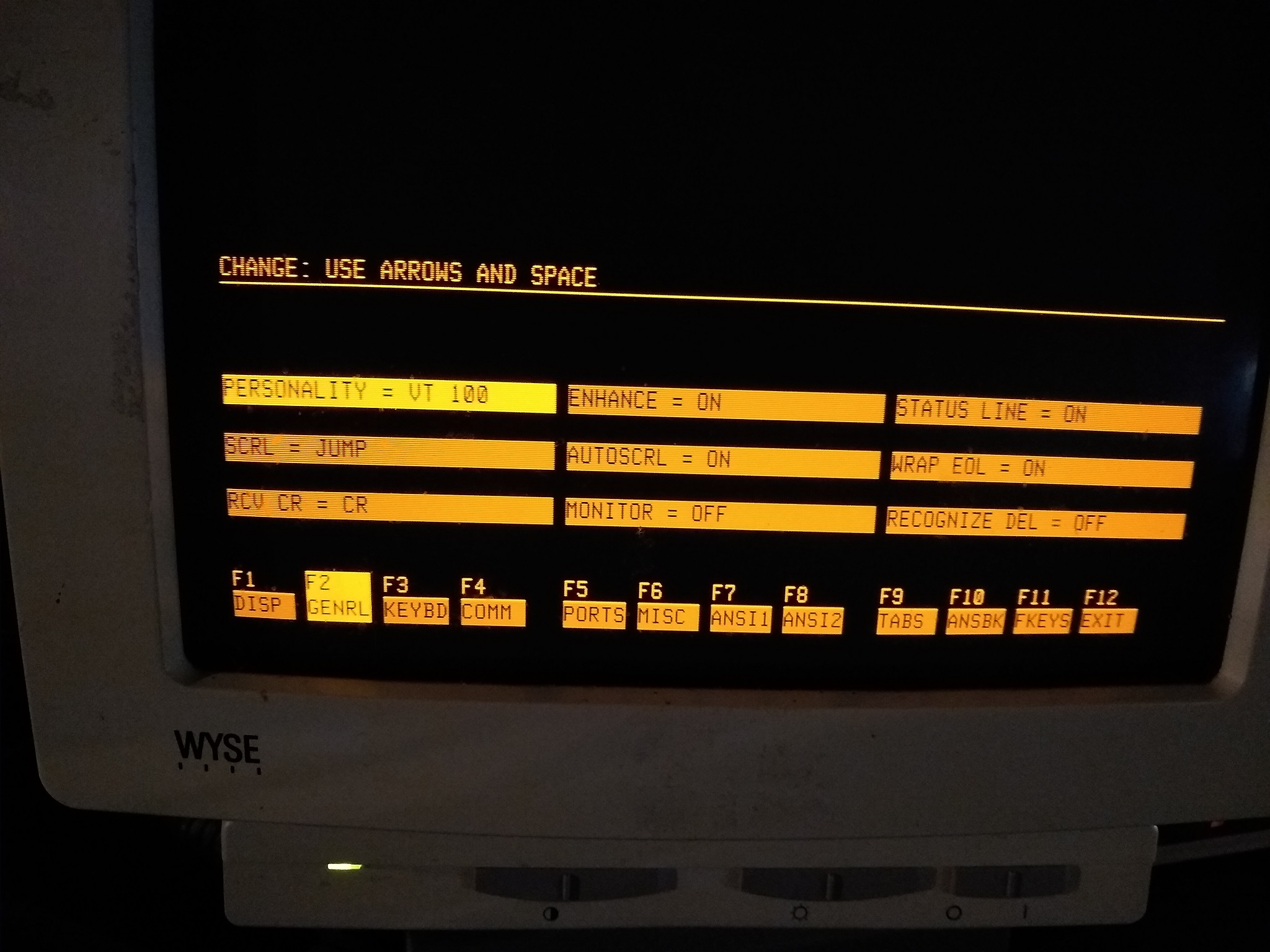
General settings.
Now, press the [F5] key to get to the Ports settings. Use the arrow keys and [Space] key in a similar manor to set MDM Baud Rate to 9600, MDM Data/Parity to 8/NONE, MDM Stop Bits to 1, and finally Host Port to MODEM PORT.
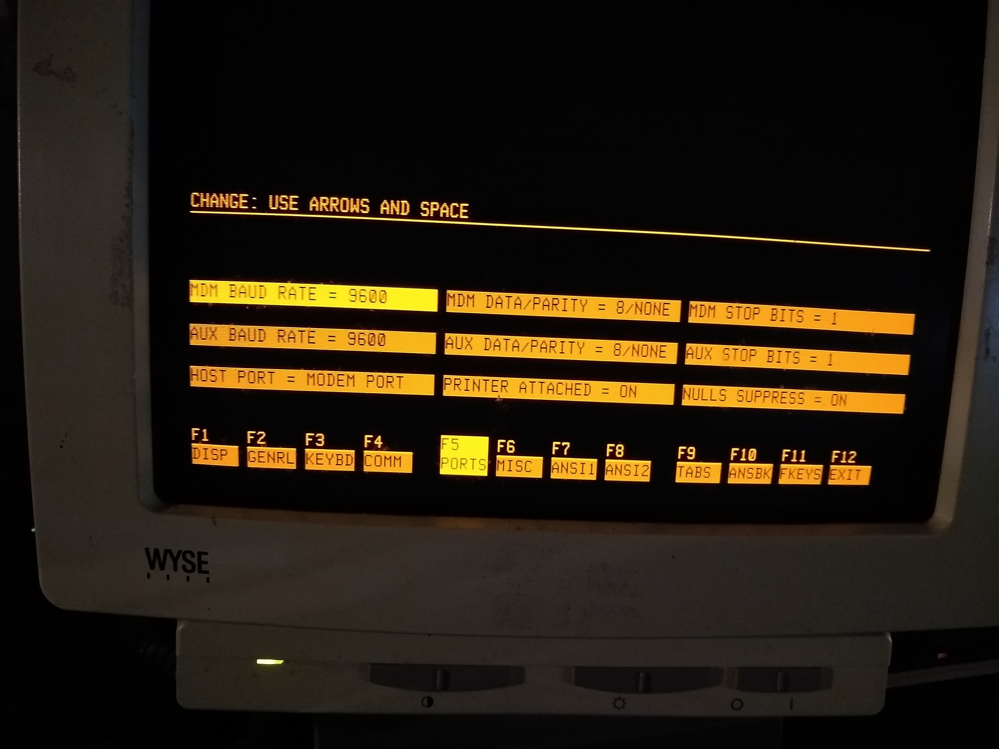
Ports settings.
These settings should work, fairly well, but I am in no way saying that these will give you the fastest connection. You may want to go through all of the settings menus to see if there is anything else you would like to configure like cursor blink and stuff like that.
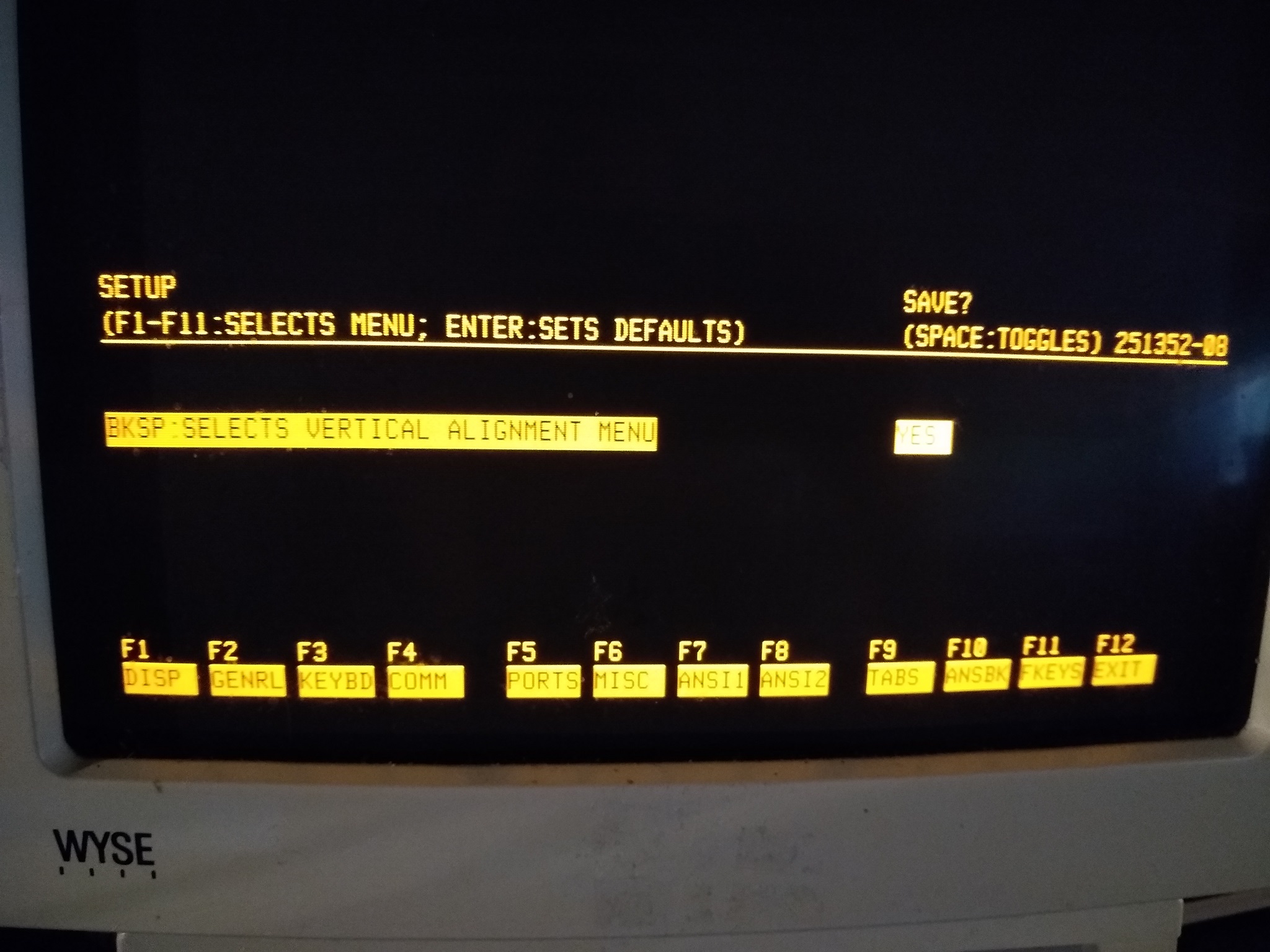
Save the settings.
When you are done, press the [F12] key to get to the Exit screen and use the [Space] button to toggle the Save option to YES. Finally, press [F12] again to save the settings.
Now, turn off the terminal so we can work on getting the Raspberry Pi ready.
Using a USB Serial Adapter
Perhaps the easiest way to connect your terminal to your Raspberry Pi is through the use of a USB to serial adapter. I ordered the inexpensive Sabrent USB 2.0 to Serial (9-Pin) DB-9 RS-232 Converter Cable from Amazon which gets the job done.
The USB Serial adapter plugged into the Pi.
After you plug the adapter into your Raspberry Pi, you will still need to configure the Pi to allow console incoming console connections from the device.
First, check to make sure your Pi recognizes the adapter:
$ ls /dev/*USB*
/dev/ttyUSB0
Now, we can leverage getty to manage the adapter and provide a console to the connecting terminal:
$ sudo systemctl enable serial-getty@ttyUSB0.service
This is really all there is to it, and this will start automatically on system boot. If you are using a different type of terminal (like a VT100), the default serial-getty service may not work for you and you will have to modify serial-getty@.service. However, the service seems to work just fine for me by default using the stock ExecStart string:
$ cat /lib/systemd/system/serial-getty@.service | grep 'ExecStart'
ExecStart=-/sbin/agetty -o '-p -- \\u' --keep-baud 115200,38400,9600 %I $TERM
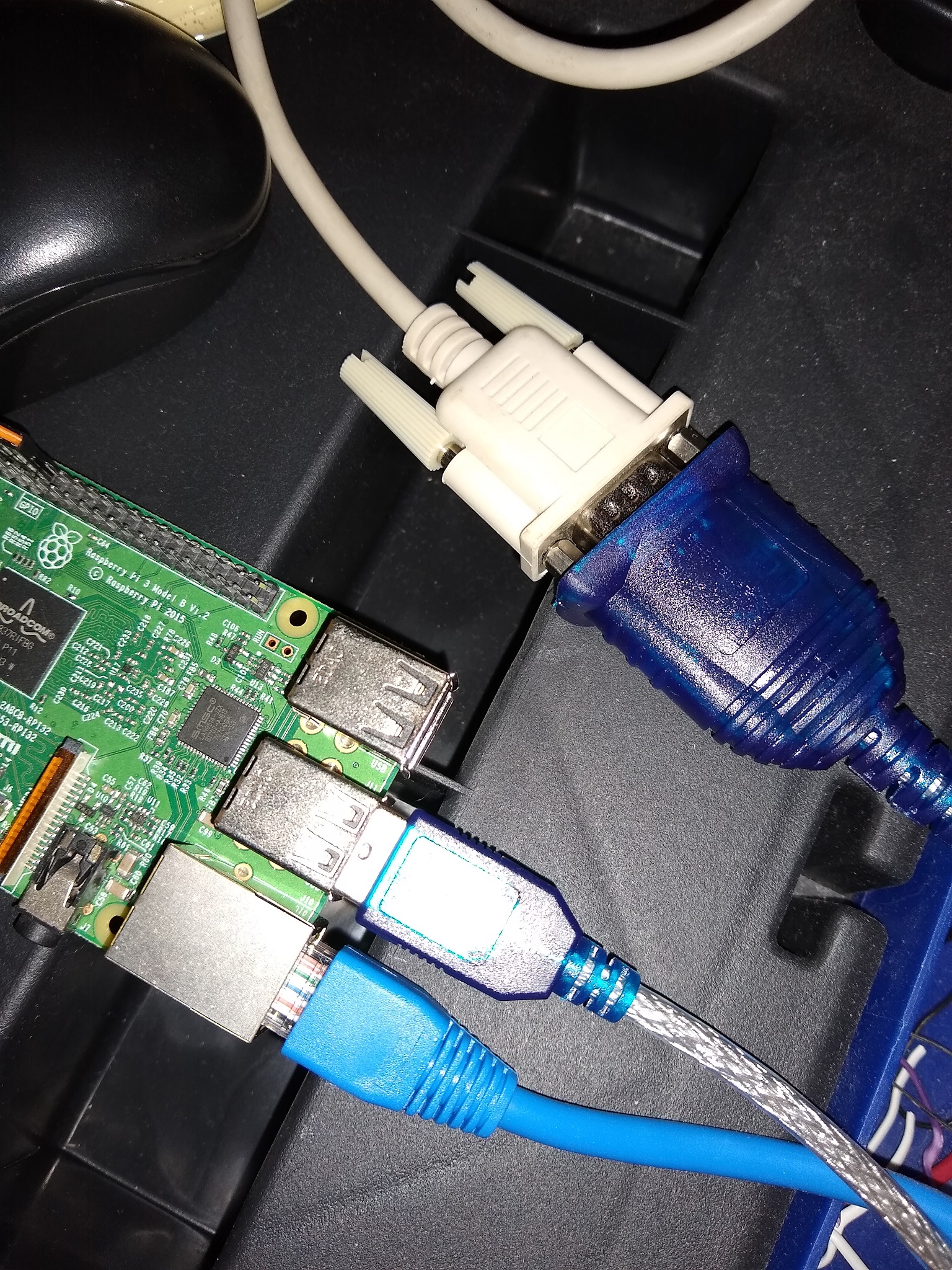
Using a USB adapter sets up the Raspberry Pi as a DTE (Data Terminal Equipment) while the terminal itself is hard-wired to be a DTE. Because of this, we will need to use a null modem adapter between the two devices to allow them to communicate. As you may have also noticed, the USB adapter provides a DE-9 connector while the terminal has only DB-25 ports. We will need to get a cable to connect the two together, and you can easily purchase an all-in-one cable with DE-9/DB-25 conversion and null modem adapter built in like the 6ft Null Modem DB9F/DB25F Molded Cable from Monoprice. Any other combination of DE-9 cable, null modem, and DE-9/DB-25 converter should also do the trick.
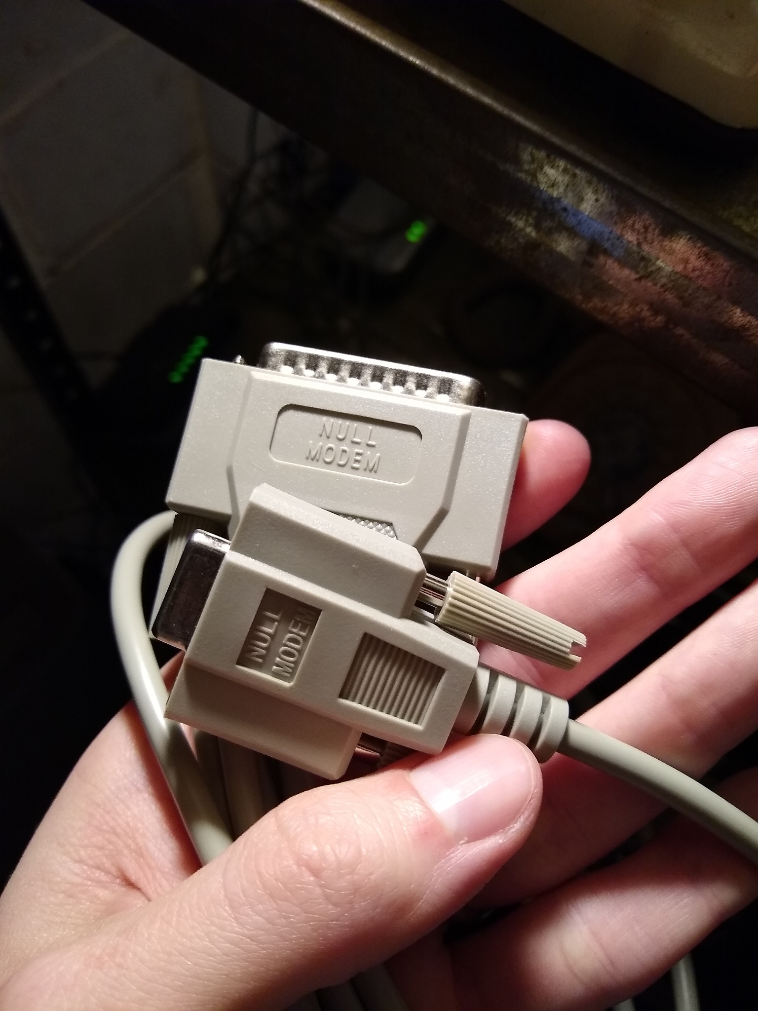
DE-9/DB-25 null modem cable.
Connecting the the Pi to the terminal is as easy as connecting the DE-9 end of the cable into the USB adapter and the DB-25 end into the Modem port on the terminal (the one on the left, not the printer port). Now, you can start up the terminal. If you are not immediately presented with a login prompt, press a key on the keyboard and the screen should spring to life.
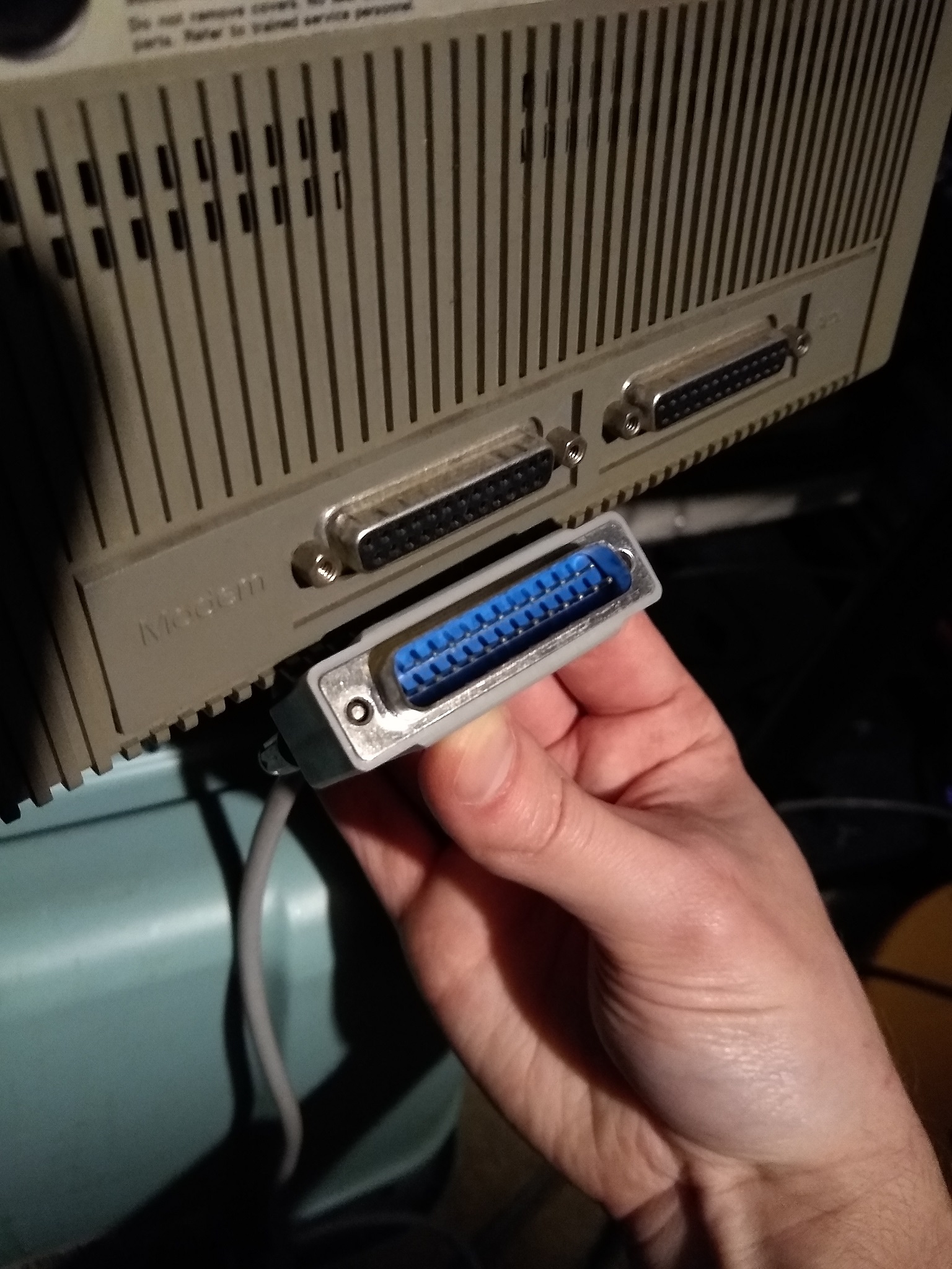
Use the Modem port on the back of the terminal.
Using the UART
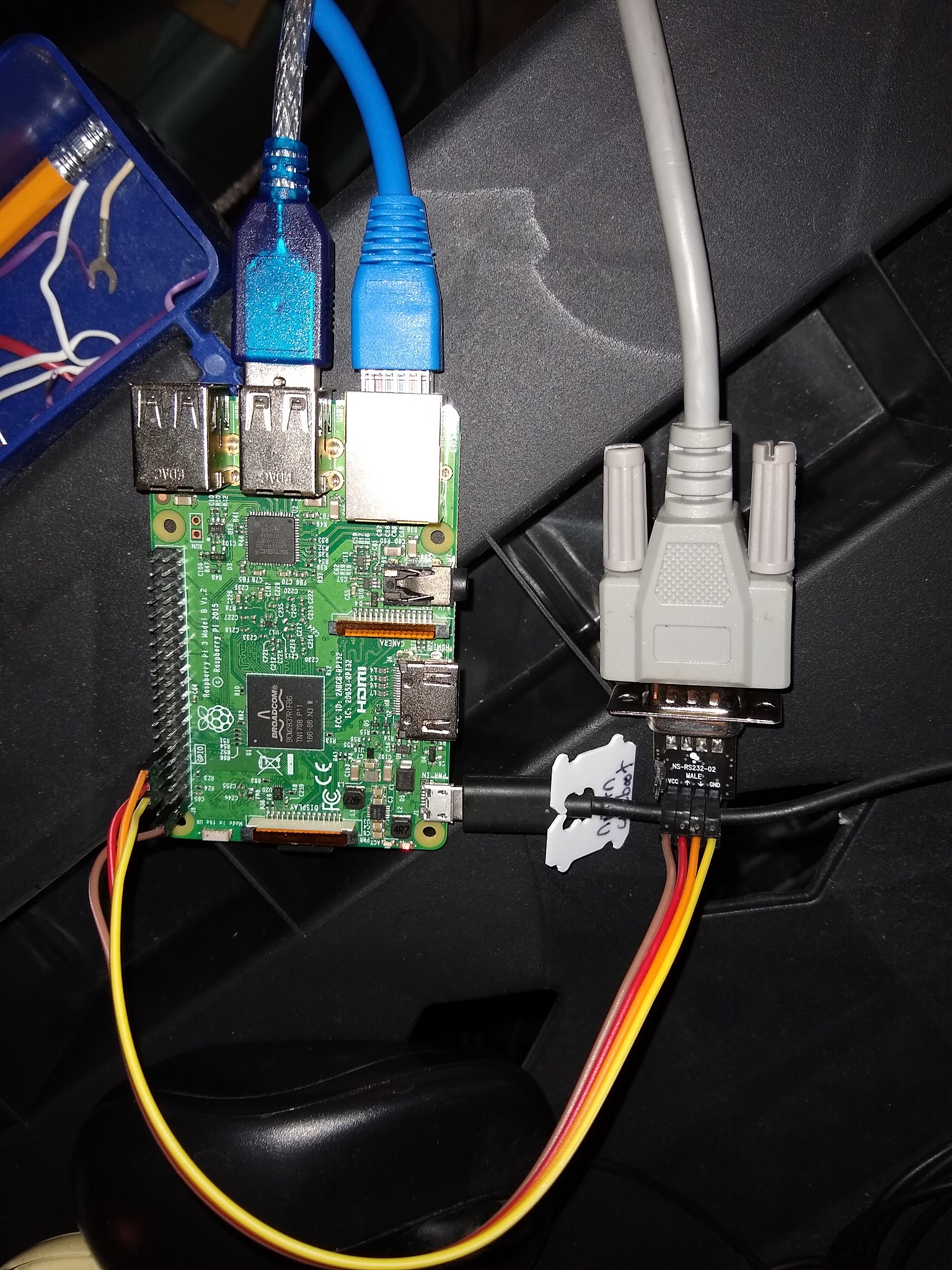
For whatever reason, I like to keep my USB ports free and like to connect a terminal to my Raspberry Pi through the UART pins. While the Raspberry Pi provides TTL at 3.3v, the terminal can only speak RS232 at 12v. To get around this, we need a little convertor board that sits between the Raspberry Pi and terminal. After a little research, I purchased the NulSom Inc. Ultra Compact RS232 to TTL Converter with Male DB9 from Amazon to serve this purpose. From the light reading I did, converters with a MAX3232 chip on them outperform older MAX232 chips. You can probably get away with a cheaper converter based on the MAX232 (though I haven’t tested it personally) but the newer MAX3232 chips are now being used in convertors that sell for a similar price. As long as your convertor can handle 3.3v, it should be safe to use with the Raspberry Pi.
This converter that I bought requires you to solder your own header pins, which are relatively easy to get and easy to install. Cheap ones from Amazon should work fine, and while you only need four pins you will likely need to buy a pack with a lot more. To connect between the soldered pins on the convertor and your Raspberry Pi, you will also need four female-to-female jumper wires like these from Amazon.
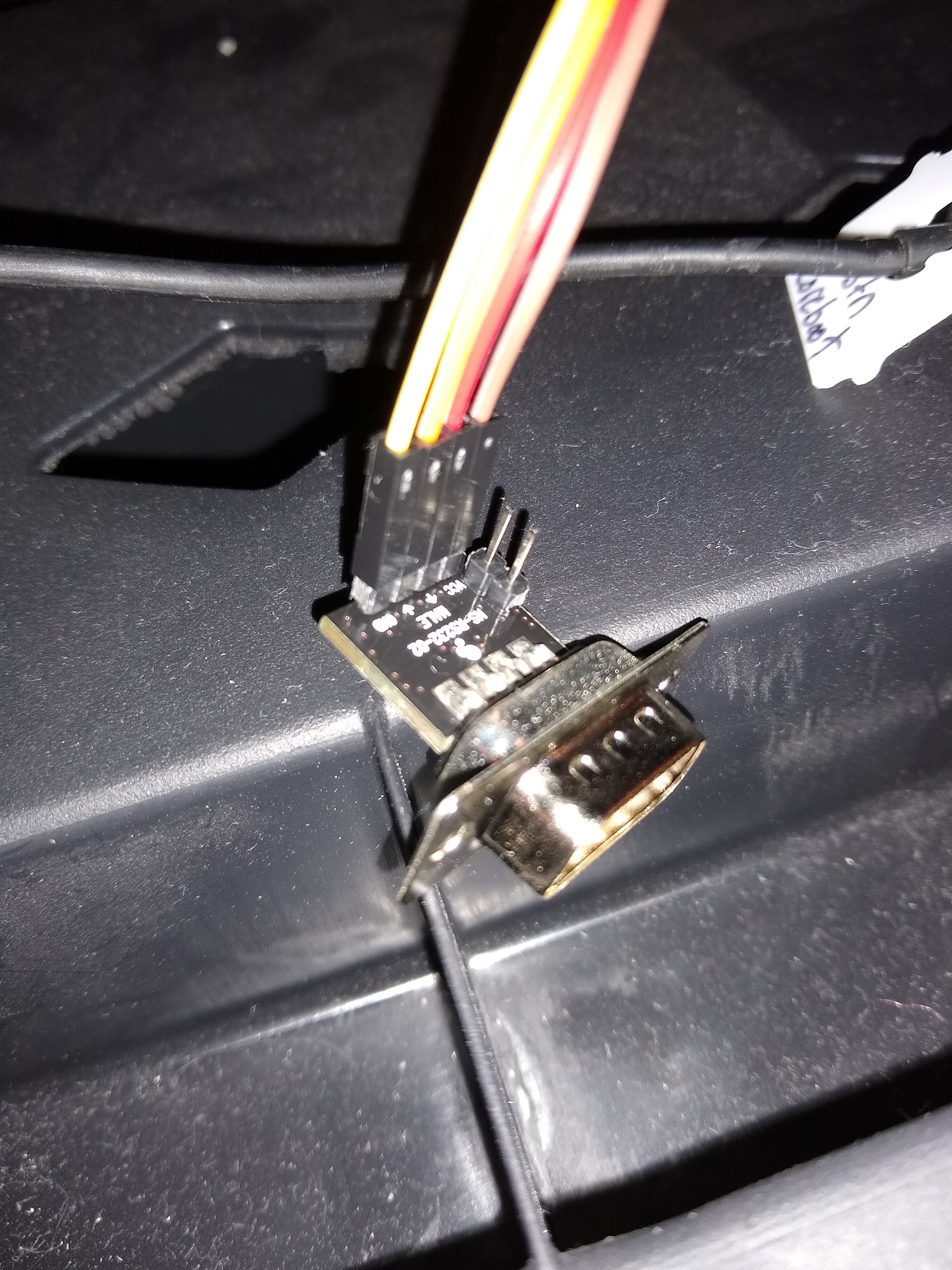
The UART/RS232 convertor with pins soldered.
Now we need to configure the Raspberry Pi to enable UART, this is as simple as making sure enable_uart=1 is present in /boot/config.txt:
$ cat /boot/config.txt
# For more options and information see
# http://rpf.io/configtxt
# Some settings may impact device functionality. See link above for details
enable_uart=1
If it isn’t already there, add it and sudo reboot the Pi.
Next, we can check if there is already a getty service running for UART to allow console connections. On the Raspberry Pi 3, the standard /dev/ttyAMA0 device is now used for Bluetooth which is a departure from previous models where it was used for communication via GPIO pins. We do however have a mini UART device (/dev/ttyS0) available which is generally seen as less-featured but perfectly fine for console connections.
When I checked my Pi, there was already a getty running for the mini UART:
$ sudo systemctl status serial-getty@ttyS0.service
● serial-getty@ttyS0.service - Serial Getty on ttyS0
   Loaded: loaded (/lib/systemd/system/serial-getty@.service; enabled-runtime; vendor preset: enabled)
   Active: active (running) since Thu 2020-07-30 00:17:17 EDT; 13h ago
     Docs: man:agetty(8)
           man:systemd-getty-generator(8)
           http://0pointer.de/blog/projects/serial-console.html
 Main PID: 542 (agetty)
    Tasks: 1 (limit: 2200)
   Memory: 140.0K
   CGroup: /system.slice/system-serial\x2dgetty.slice/serial-getty@ttyS0.service
           └─542 /sbin/agetty -o -p -- \u --keep-baud 115200,38400,9600 ttyS0 vt220

Jul 30 00:17:17 raspberrypi systemd[1]: Started Serial Getty on ttyS0.
If you get a message that your service is disabled, it is easy to enable and start:
$ sudo systemctl enable serial-getty@ttyS0.service
$ sudo systemctl start serial-getty@ttyS0.service
This will not only start getty to monitor connections via mini UART, but also automatically launch this service every time the Raspberry Pi is rebooted. As I mentioned in the USB adapter section of this post, if you are using a different type of terminal besides Wyse, you may have to update the serial-getty service to get things working properly.
Your convertor should have four pins on it: GND, VCC, RX, and TX. Now, with the Pi off, use the jumper wires to connect the 3.3v pin on the Raspberry Pi to the VCC pin on the convertor, and also connect up the GNDs. Then, connect the Pi’s TX pin to the convertor’s RX pin and the Pi’s RX pin to the convertor’s TX pin.
Edge of pi (furthest from you)
                 (UART)
   L           GND TX  RX                           CS
   E            |   |   |                           |
   F +---------------------------------------------------------------------------------+
   T |  x   x   x   x   x   x   x   x   x   x   x   x   x   x   x   x   x   x   x   x  |
     |  x   x   x   x   x   x   x   x   x   x   x   x   x   x   x   x   x   x   x   x  |
   E +----------------------------------^---^---^---^-------------------------------^--+
   D                                    |   |   |   |                               |
   G                                   3.3V MOSIMISO|                              GND
   E                                 (VCC)         CLK
     Body of Pi (closest to you)
(Raspberry Pi 3 pinout, via github.com/merge/skulls/blob/master/x230/README.md)
The convertor connected to the RPi.
Again, Using this convertor sets up the Raspberry Pi as a DTE (Data Terminal Equipment) while the terminal itself is hard-wired to be a DTE. Because of this, we will need to use a null modem adapter between the two devices to allow them to communicate. As you may have also noticed, the convertor provides a DE-9 connector while the terminal has only DB-25 ports. We will need to get a cable to connect the two together, and you can easily purchase an all-in-one cable with DE-9/DB-25 conversion and null modem adapter built in like the 6ft Null Modem DB9F/DB25F Molded Cable from Monoprice. Any other combination of DE-9 cable, null modem, and DE-9/DB-25 converter should also do the trick.
DE-9/DB-25 null modem cable.
Connecting the the Pi to the terminal is as easy as connecting the DE-9 end of the cable into the convertor and the DB-25 end into the Modem port on the terminal (the one on the left, not the printer port).
Use the Modem port on the back of the terminal.
Now you can power on the Pi and give it a few seconds to boot up. Next, you can start up the terminal. If you are not immediately presented with a login prompt, press a key on the keyboard and the screen should spring to life.
Sources
- https://dave.cheney.net/2014/01/05/a-real-serial-console-for-your-raspberry-pi
- https://www.circuits.dk/setup-raspberry-pi-3-gpio-uart/
- https://www.rogerirwin.co.nz/open-source/enabling-a-serial-port-console/
- https://www.raspberrypi.org/forums/viewtopic.php?t=147370
- https://www.raspberrypi.org/forums/viewtopic.php?t=217583